Skip to content


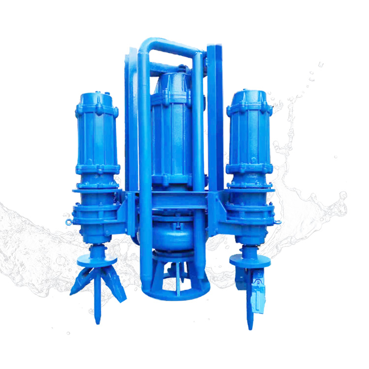
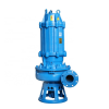
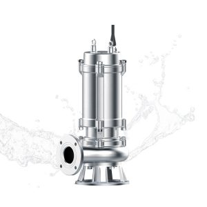
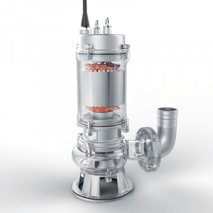
Submersible slurry pump has been comprehensively optimized and innovatively designed in the aspects of hydraulic model, sealing technology, mechanical structure, protection control, etc.


More Product Details
TUSSU®ZTU Submersible slurry pump has been comprehensively optimized and innovatively designed in the aspects of hydraulic model, sealing technology, mechanical structure, protection control, etc. This product has a simple structure, convenient installation, safe and reliable use, and long life. Submersible pumps do not need to build complex ground pump rooms and fixtures underwater, no noise and vibration, and the site is cleaner. The submersible sewage pump is a submersible sewage pump that can tear, cut and discharge the long fibers, bags, belts, grass, cloth and other materials in the sewage, and then discharge smoothly. It is especially suitable for conveying liquids containing hard solids and fibrous materials and special Dirty, sticky, slippery liquid.
TUSSU®ZTU Submersible Slurry Pump Performance Parameter
| Model | Flow Rate (m³/h) | Head (m) | Power (kW) | Rotational Speed (r/min) | Max Particle Pass Size (mm) |
|---|---|---|---|---|---|
| ZTU40-21 | 9.5 | 17 | 4 | 1,450 | 8 |
| ZTU40-21 | 20.3 | 15.3 | 4 | 1,450 | 8 |
| ZTU40-21 | 26 | 14.1 | 4 | 1,450 | 8 |
| ZTU40-20 | 10.44 | 11.5 | 1.5 | 1,450 | 12 |
| ZTU40-20 | 18 | 10.5 | 2.2 | 1,450 | 12 |
| ZTU40-20 | 25.2 | 9 | 3 | 1,450 | 12 |
| ZTU40-20 | 16.6 | 57.5 | 11 | 2,950 | 8 |
| ZTU40-20 | 33.3 | 5 | 15 | 2,950 | 8 |
| ZTU40-20 | 37.1 | 47.1 | 15 | 2,950 | 8 |
| ZTU40-20 | 8.1 | 13.7 | 1.5 | 1,450 | 8 |
| ZTU40-20 | 16.3 | 12 | 2.2 | 1,450 | 8 |
| ZTU40-20 | 18.1 | 11.2 | 2.2 | 1,450 | 8 |
| ZTU-40PV | 7.2 | 5.5 | 1.1 | 980 | 8 |
| ZTU-40PV | 12.6 | 5 | 1.1 | 980 | 8 |
| ZTU-40PV | 18.0 | 4.3 | 1.1 | 980 | 8 |
| ZTU-40PV | 10.44 | 11.5 | 1.5 | 1,450 | 8 |
| ZTU-40PV | 18.0 | 10.5 | 2.2 | 1,450 | 8 |
| ZTU-40PV | 25.2 | 9 | 3 | 1,450 | 8 |
| ZTU40-35 | 19.7 | 48 | 18.5 | 1,450 | 8 |
| ZTU40-35 | 39.4 | 41.7 | 18.5 | 1,450 | 8 |
| ZTU40-35 | 47.6 | 35.8 | 18.5 | 1,450 | 8 |
| ZTU40-35 | 12.9 | 20.5 | 5.5 | 980 | 8 |
| ZTU40-35 | 25.7 | 17.8 | 5.5 | 980 | 8 |
| ZTU40-35 | 31.1 | 15.3 | 5.5 | 980 | 8 |
| ZTU40-25 | 10.1 | 21.5 | 5.5 | 1,450 | 8 |
| ZTU40-25 | 18.4 | 19 | 5.5 | 1,450 | 8 |
| ZTU40-25 | 22.9 | 16.8 | 5.5 | 1,450 | 8 |
| ZTU40-25 | 6.6 | 9.2 | 1.5 | 980 | 8 |
| ZTU40-25 | 12 | 8.1 | 1.5 | 980 | 8 |
| ZTU40-25 | 15 | 7.2 | 1.5 | 980 | 8 |
| ZTU40-25A | 35.5 | 88.6 | 30 | 2,950 | 8 |
| ZTU40-25A | 58.8 | 73.5 | 37 | 2,950 | 8 |
| ZTU40-25A | 74.7 | 60.8 | 37 | 2,950 | 8 |
| ZTU40-25A | 17.3 | 21.1 | 4 | 1,450 | 8 |
| ZTU40-25A | 28.7 | 17.5 | 5.5 | 1,450 | 8 |
| ZTU40-25A | 36.5 | 14.5 | 5.5 | 1,450 | 8 |
| ZTU50-30 | 34 | 36.3 | 11 | 1,450 | 8 |
| ZTU50-30 | 55 | 32 | 15 | 1,450 | 8 |
| ZTU50-30 | 78 | 26.4 | 18.5 | 1,450 | 8 |
| ZTU50-30 | 22 | 15.7 | 4 | 980 | 8 |
| ZTU50-30 | 36 | 13.8 | 5.5 | 980 | 8 |
| ZTU50-30 | 51 | 11.4 | 5.5 | 980 | 8 |
| ZTU50-20 | 10.8 | 4.3 | 11 | 980 | 8 |
| ZTU50-20 | 15.6 | 3.7 | 11 | 980 | 8 |
| ZTU50-20 | 24 | 2.4 | 11 | 980 | 8 |
| ZTU50-20 | 17.1 | 10.7 | 4 | 1,450 | 8 |
| ZTU50-20 | 24.7 | 9.2 | 4 | 1,450 | 8 |
| ZTU50-20 | 38 | 6 | 4 | 1,450 | 8 |
| ZTU50-20 | 37 | 46.2 | 30 | 2,950 | 8 |
| ZTU50-20 | 56 | 38.3 | 30 | 2,950 | 8 |
| ZTU50-20 | 70 | 24.3 | 30 | 2,950 | 8 |
| ZTU50-20 | 18 | 11 | 4 | 1,450 | 8 |
| ZTU50-20 | 28 | 9.1 | 4 | 1,450 | 8 |
| ZTU50-20 | 34 | 5.8 | 4 | 1,450 | 8 |
| ZTU65-S24Q | 26.28 | 12.8 | 3 | 1,450 | 8 |
| ZTU65-S24Q | 46.8 | 11.4 | 4 | 1,450 | 8 |
| ZTU65-S24Q | 65.88 | 9.8 | 5.5 | 1,450 | 8 |
| ZTU65-S24Q | 39.6 | 29.3 | 18.5 | 980 | 8 |
| ZTU65-S24Q | 70 | 26 | 22 | 980 | 8 |
| ZTU65-S24Q | 100 | 22.7 | 22 | 980 | 8 |
| ZTU65D-30 | 44 | 35.6 | 15 | 1,450 | 8 |
| ZTU65D-30 | 79 | 32.6 | 18.5 | 1,450 | 8 |
| ZTU65D-30 | 99 | 30.7 | 22 | 1,450 | 8 |
| ZTU65D-30 | 29 | 15.2 | 5.5 | 980 | 8 |
| ZTU65D-30 | 51 | 13.9 | 5.5 | 980 | 8 |
| ZTU65D-30 | 64 | 13.1 | 5.5 | 980 | 8 |
| ZTU65-A30 | 47 | 34.8 | 11 | 1,450 | 8 |
| ZTU65-A30 | 62 | 34 | 15 | 1,450 | 8 |
| ZTU65-A30 | 79 | 32 | 15 | 1,450 | 8 |
| ZTU65-A27 | 42 | 28.2 | 11 | 1,450 | 8 |
| ZTU65-A27 | 56 | 27.5 | 11 | 1,450 | 8 |
| ZTU65-A27 | 71 | 26 | 11 | 1,450 | 8 |
| ZTU80-36 | 86 | 47.1 | 30 | 1,450 | 12 |
| ZTU80-36 | 151 | 42 | 37 | 1,450 | 12 |
| ZTU80-36 | 167 | 40 | 37 | 1,450 | 12 |
| ZTU80-36 | 56 | 20.2 | 11 | 980 | 12 |
| ZTU80-36 | 99 | 18 | 11 | 980 | 12 |
| ZTU80-36 | 109 | 17.1 | 11 | 980 | 12 |
| ZTU65-40 | 71 | 63.2 | 37 | 1,450 | 8 |
| ZTU65-40 | 141 | 57.5 | 45 | 1,450 | 8 |
| ZTU65-40 | 159 | 54.6 | 45 | 1,450 | 8 |
| ZTU65-40 | 47 | 27.1 | 11 | 980 | 8 |
| ZTU65-40 | 92 | 24.7 | 15 | 980 | 8 |
| ZTU65-40 | 104 | 23.5 | 15 | 980 | 8 |
| ZTU65-30 | 38 | 34.7 | 18.5 | 1,450 | 8 |
| ZTU65-30 | 58 | 31.9 | 18.5 | 1,450 | 8 |
| ZTU65-30 | 98 | 26 | 18.5 | 1,450 | 8 |
| ZTU65-30 | 25 | 14.8 | 5.5 | 980 | 8 |
| ZTU65-30 | 38 | 13.6 | 5.5 | 980 | 8 |
| ZTU65-30 | 64 | 11.1 | 5.5 | 980 | 8 |
| ZTU100-33 | 119 | 41.6 | 30 | 1,450 | 14 |
| ZTU100-33 | 202 | 37.8 | 37 | 1,450 | 14 |
| ZTU100-33 | 225 | 36.5 | 45 | 1,450 | 14 |
| ZTU100-40Q | 82.8 | 24 | 37 | 980 | 14 |
| ZTU100-40Q | 147 | 22.5 | 45 | 980 | 14 |
| ZTU100-40Q | 214 | 20 | 22 | 980 | 14 |
| ZTU80-45 | 124 | 80.5 | 75 | 1,450 | 12 |
| ZTU80-45 | 235 | 66 | 75 | 1,450 | 12 |
| ZTU80-45 | 284 | 56 | 75 | 1,450 | 12 |
| ZTU80-45 | 81 | 34.6 | 22 | 980 | 12 |
| ZTU80-45 | 154 | 28.3 | 22 | 980 | 12 |
| ZTU80-45 | 186 | 24 | 22 | 980 | 12 |
| ZTU80-36 | 105 | 45.5 | 45 | 1,450 | 12 |
| ZTU80-36 | 144 | 41.4 | 45 | 1,450 | 12 |
| ZTU80-36 | 201 | 32.5 | 45 | 1,450 | 12 |
| ZTU80-36 | 69 | 19.5 | 15 | 980 | 12 |
| ZTU80-36 | 94 | 17.8 | 15 | 980 | 12 |
| ZTU80-36 | 132 | 14 | 15 | 980 | 12 |
| ZTU100-40 | 129 | 61 | 45 | 1,450 | 32 |
| ZTU100-40 | 219 | 56.1 | 75 | 1,450 | 32 |
| ZTU100-40 | 268 | 53.6 | 75 | 1,450 | 32 |
| ZTU100-40 | 85 | 26.2 | 15 | 980 | 32 |
| ZTU100-40 | 144 | 24.1 | 22 | 980 | 32 |
| ZTU100-40 | 176 | 23 | 22 | 980 | 32 |
| ZTU100-35 | 163 | 46 | 45 | 1,450 | 14 |
| ZTU100-35 | 278 | 41.5 | 55 | 1,450 | 14 |
| ZTU100-35 | 323 | 39.2 | 55 | 1,450 | 14 |
| ZTU100-35 | 107 | 19.7 | 15 | 980 | 14 |
| ZTU100-35 | 182 | 17.8 | 18.5 | 980 | 14 |
| ZTU100-35 | 212 | 16.8 | 18.5 | 980 | 14 |
| ZTU100-34 | 157 | 35.8 | 45 | 1,450 | 14 |
| ZTU100-34 | 214 | 32.6 | 45 | 1,450 | 14 |
| ZTU100-34 | 293 | 24.4 | 45 | 1,450 | 14 |
| ZTU100-34 | 103 | 15.8 | 15 | 980 | 14 |
| ZTU100-34 | 140 | 14 | 15 | 980 | 14 |
| ZTU100-34 | 192 | 10.5 | 15 | 980 | 14 |
| ZTU100-60 | 152 | 147 | 160 | 1,450 | 32 |
| ZTU100-60 | 256 | 138.5 | 200 | 1,450 | 32 |
| ZTU100-60 | 305 | 131.7 | 220 | 1,450 | 32 |
| ZTU100-60 | 101 | 65 | 45 | 980 | 32 |
| ZTU100-60 | 170 | 61.2 | 75 | 980 | 32 |
| ZTU100-60 | 203 | 58.1 | 75 | 980 | 32 |
| ZTU100-45A | 100 | 83.5 | 55 | 1,450 | 32 |
| ZTU100-45A | 195 | 71.6 | 75 | 1,450 | 32 |
| ZTU100-45A | 228 | 66 | 90 | 1,450 | 32 |
| ZTU100-45A | 66 | 36.6 | 18.5 | 980 | 32 |
| ZTU100-45A | 129 | 31.4 | 30 | 980 | 32 |
| ZTU100-45A | 151 | 29 | 30 | 980 | 32 |
| ZTU100-45B | 88 | 76.4 | 55 | 1,450 | 32 |
| ZTU100-45B | 166 | 65.2 | 75 | 1,450 | 32 |
| ZTU100-45B | 219 | 54.3 | 90 | 1,450 | 32 |
| ZTU100-45B | 57 | 32.8 | 18.5 | 980 | 32 |
| ZTU100-45B | 109 | 28 | 22 | 980 | 32 |
| ZTU100-45B | 144 | 23.3 | 30 | 980 | 32 |
| ZTU200-45 | 230 | 33.5 | 75 | 980 | 45 |
| ZTU200-45 | 396 | 30.2 | 90 | 980 | 45 |
| ZTU200-45 | 561 | 25.4 | 110 | 980 | 45 |
| ZTU150-50 | 123 | 44.6 | 37 | 980 | 45 |
| ZTU150-50 | 221 | 40.1 | 45 | 980 | 45 |
| ZTU150-50 | 279 | 37.2 | 55 | 980 | 45 |
| ZTU150-50 | 92 | 24.7 | 15 | 740 | 45 |
| ZTU150-50 | 165 | 22.3 | 22 | 740 | 45 |
| ZTU150-50 | 208 | 20.6 | 30 | 740 | 45 |
| ZTU150-35 | 198 | 17.9 | 30 | 980 | 15 |
| ZTU150-35 | 332 | 13.2 | 30 | 980 | 15 |
| ZTU150-35 | 364 | 12.1 | 30 | 980 | 15 |
| ZTU150-35 | 147 | 10 | 11 | 740 | 15 |
| ZTU150-35 | 247 | 7.3 | 11 | 740 | 15 |
| ZTU150-35 | 271 | 6.7 | 11 | 740 | 15 |
| ZTU150-35 | 119 | 6.5 | 7.5 | 590 | 15 |
| ZTU150-35 | 200 | 4.8 | 7.5 | 590 | 15 |
| ZTU150-35 | 219 | 4.4 | 7.5 | 590 | 15 |
| ZTU300-60 | 878 | 30 | 132 | 740 | 65 |
| ZTU200-45 | 276 | 30.4 | 45 | 980 | 50 |
| ZTU200-45 | 551 | 25.6 | 55 | 980 | 50 |
| ZTU200-45 | 638 | 22.8 | 75 | 980 | 50 |
| ZTU200-45 | 206 | 17 | 22 | 740 | 50 |
| ZTU200-45 | 410 | 14.2 | 30 | 740 | 50 |
| ZTU200-45 | 475 | 12.7 | 30 | 740 | 50 |
| ZTU150-60 | 218 | 66 | 90 | 980 | 45 |
| ZTU150-60 | 381 | 60 | 110 | 980 | 45 |
| ZTU150-60 | 466 | 56.6 | 101.8 | 980 | 45 |
| ZTU150-60 | 162 | 36.5 | 37 | 740 | 45 |
| ZTU150-60 | 284 | 33.2 | 45 | 740 | 45 |
| ZTU150-60 | 347 | 31.4 | 55 | 740 | 45 |
| ZTU150-55 | 280 | 53.7 | 90 | 980 | 45 |
| ZTU150-55 | 517 | 48 | 110 | 980 | 45 |
| ZTU150-55 | 630 | 46 | 132 | 980 | 45 |
| ZTU150-55 | 209 | 30 | 37 | 740 | 45 |
| ZTU150-55 | 387 | 26.8 | 45 | 740 | 45 |
| ZTU150-55 | 471 | 25.7 | 55 | 740 | 45 |
TUSSU®ZTU Submersible Slurry Pump Structure

- Pump Body and Impeller
The pump body and impeller are precisely selected and matched based on rigorous experimental testing data. Both components are cast from high-chromium, wear-resistant, and corrosion-resistant alloys, ensuring exceptional flow capacity, high efficiency, and a flat power curve that effectively prevents overloading. Precision balancing of the impeller minimizes vibration and ensures exceptionally smooth operation.
- Agitator (Mixer Wheel)
An agitator is positioned at the absolute bottom of the pump, capable of stirring settled sludge and sediment at the waterbed into a turbulent slurry before extraction. This design seamlessly integrates submersion, agitation, sand blowing, and suction into a single unit, significantly boosting sand suction efficiency and ensuring more thorough dredging results.
- Submersible Motor
The system utilizes a specially engineered submersible motor featuring an IPX8 protection rating and Class F insulation. It allows for a high permissible temperature rise; under normal temperature conditions, the motor’s insulation lifespan is substantially prolonged. The underwater environment provides excellent natural cooling effects, maintaining a low actual temperature rise and extending the operational life of the motor insulation.
- Motor Cooling Mechanism
Heat generated by the motor is dissipated directly through the outer casing. As long as the medium completely submerges the motor stator shell, the pump can operate safely and reliably. Greater submersion depth enhances the efficiency of the motor cooling process.
- Shaft Sealing
The motor shaft utilizes two independent, series-connected mechanical seals to form a dual-layered, reliable barrier. The first seal is exposed directly to the pumped medium, and its sealing faces compress tighter as the medium pressure increases, effectively preventing water from entering the oil chamber. The second seal is located inside the oil chamber to prevent oil from penetrating into the internal motor cavity. If the first seal fails (due to harsher operating conditions), the second seal remains fully capable of preventing oil-water mixtures from entering the motor. The bellows-type mechanical seal, paired with an innovative structural cavity design, drastically improves sealing reliability. Under normal operation, the system guarantees a maintenance-free running time exceeding 8,000 hours.
- Oil Chamber
The oil chamber acts as a vital defensive barrier preventing the medium from penetrating along the shaft into the motor, blocking fluid from reaching the electrical poles. In the event of a primary mechanical seal leak, the oil chamber cushions and absorbs the incoming medium, ensuring it cannot directly enter the motor. Simultaneously, it lubricates and cools the friction faces of both independent seals to ensure stable seal operation, while also carrying away heat generated by the lower bearing and parts of the motor.
- Bearings
The lower assembly features heavy-duty double-row angular contact ball bearings with excellent load-bearing capacity. Working in tandem with the upper deep groove ball bearing, they form a highly reliable support system for the combined motor-pump shaft. This setup offers substantial load margins against the radial, axial, and transient forces generated during slurry pumping operations, ensuring stable unit rotation and a long operating life.
- Cables and Cable Sealing
- The power connection consists of a heavy-duty, sewage-resistant, rubber-sheathed flexible cable. The cable core cross-section is specifically sized for long-term reliable operation under a 40°C ambient temperature and full-load motor power. If the slurry pump operates below full-load capacity or in ambient temperatures under 40°C, the cable’s operational lifespan will be further extended.
- A compression seal is fitted between the outer rubber sheath of the cable and the motor gland cover, preventing any medium from leaking into the internal motor cavity through the interface between the cable and the motor.
- The area between the outer cable sheath and the inner cores is vulcanized with rubber. Even if the outer rubber jacket is accidentally cut or punctured, it still effectively prevents the medium from entering the motor interior through the core wire gaps.
- Motor Outer Housing
The motor casing, upper end-cover, and gland covers constitute the robust outer housing assembly. Reliable static seals are utilized at all component joints and mating surfaces. Every single unit undergoes stringent hydrostatic pressure testing prior to factory dispatch to ensure absolute, leak-free performance.
- Internal Safety Protection Systems (Activated via Dedicated Control Panel)
- Oil-Water Probe: Installed inside the oil chamber, it continuously monitors for fluid leakage past the primary (medium-side) mechanical seal. When leaked medium enters the oil chamber and reaches a preset threshold ratio, it triggers an alarm signal.
- Float Switch: Installed directly inside the motor chamber, it detects fluid leakage past the secondary mechanical seal. If oil or an oil-water mixture penetrates into the motor cavity, the float switch immediately issues an alarm signal and shuts down the pump.
- Thermal Protection Elements: Embedded directly within the motor stator windings. If the motor experiences sustained overloading or if the windings overheat due to other operational anomalies, these elements trigger an alarm signal and safely shut down the pump once a critical temperature threshold is reached.
- External Control System
The matching dedicated control panel processes various diagnostic and status signals originating from the pump interior. It delivers comprehensive control, automated protection, and synchronized audio-visual alarms. It effortlessly supports multiple automated control modes for both single-pump and multi-pump configurations.
| Notice to Users: When sourcing or utilizing a self-provided control panel, users must contact our Company’s Professional Control System Division for technical coordination, ensuring the proper installation of the matched protection controllers within the custom panel assembly. |
- Optional Configurations
- Forced Cooling System: A specialized metal jacket/sleeve can be fitted around the outer motor casing to introduce an external cooling water circulation loop, achieving highly effective forced cooling performance.